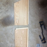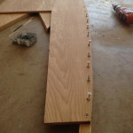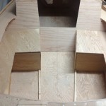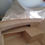
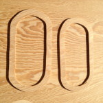
 To begin making the ports I started with creating a stencil out of styrofoam. I used two one quart cans side by side to get the rounded edges and then just drew lines between them to get the shape. Then cut out enough for all the ports.
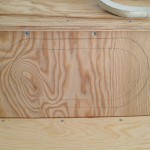
 Then I drew an outline of were I wanted the ports to line up prior to cutting into the cabin walls.
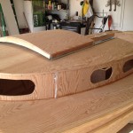 Then all the portholes were cut.

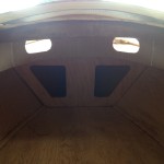 Notice I added two extra portholes in the front for better visibility from inside.

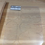 All the porthole rings cut and stained and all the plexiglass marked for cutting.
*Note* Plexiglass was too brittle and cracked easy, so I changed it out for Lexan. Cost a little more but was easier to cut and much stronger.
 You may have noticed in the above picture that there are more porthole rings than portholes. This is because I am making opening windows with an outside screen.

 The porthole windows installed with nice brass locking fixtures.
Unfortunately the two forward portholes are too curved to make functional opening windows, so they will remain fixed ports.
Hatch Box

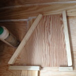 Side walls are measured and cut, with stringers attached.

 Stringers all attached with glue in place, then everything is screwed together.
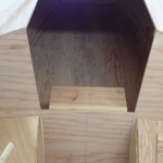
 Different views with cover in place. I decided to make the hatch box slightly smaller than the width of the opening, because I plan to use the box for housing the electrical switches and want easy access.

 Here are the switches for all the electrical components. There is a matching switch on the opposite side of the box and not pictured is the volt meter, which is mounted in the center of the box just under the lid for easy read access.
Cockpit Seats
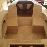
 Installing the cockpit seats begins with stringers and the side walls of the seats.
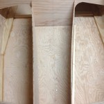
 Here is a head on shot of the side walls. After setting these in place I decided there was too little foot room at the back of the boat so I decided to look for a different option. After digging through the internet and checking out some of the builders blogs I found two different Weekenders “Molly” and “Spiritwind” that had great ideas for seating. Sooo, I put my engineering and analytical skills to the test and build my seats with no guide other than these examples. I did however keep notes and if anyone is interested, I will be glad to share them.
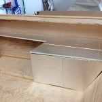 First I made a styrofoam cutout of what I wanted the seats to look like. This included a side wall, back wall and top/seat.
 Stringers are fabricated and placed into position.
Hull Assembly
There are multiple parts to the hull assembly process. These all include:
Cabin
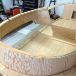
 Cabin construction starts with stringers installed along the underside of the deck opening and the cabin wall is attached. Stringers are also attached to the inside of the cabin wall for placement of the cabin roof.

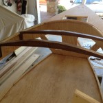 Rafters were previous cut, stained and varnished, along with custom bases, then all were installed.

 The cabin roof installation was fun to glue and screw down. I started in the center and worked outward, sitting on the roof itself and would slide outward with every screw placement.

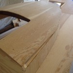 The plan warns that there will be a small shortage, and to adjust for this, you will need a small triangle of plywood as a filler.
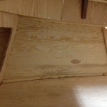 View of the inside of the cabin walls and hull side. You can see all the stringers and the custom rafter bases. The stringers were all cut in curves out of scrap stock. This was much easier that trying to bend them into place.
Hatches
Bowsprit
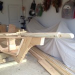
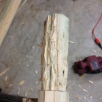 To make the end of the bowsprit rounded, I used a hammer and chisel to get the rough shape. Then used a belt sander to finish out the shape, and fine tuned it by hand sanding.
Bits
 Here is the best picture of the bits in a test fit.
Mast Box
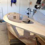 Placement of the mast box will be in the gap between the stringers in front of the forward bulkhead. This will make a nice tight fit for the box.
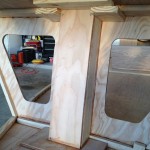
 Here is how it is supposed to look when finished.
 Well when I went to cut the opening in the deck for the mast, I was off center by nearly a 1/2″, so I had make some modifications. To make a long story short, I took out the side wall in the direction I needed to shift the box for it to be center, and then filled in the opposite side with the appropriate thickness of plywood.
Rub Rails

 Port and Starboard Rub rails completed.
 Installing the rub rails did require the help of an extra pair of hands. The rails are made up of 1×2 trim that are 16′ long. I first used the board itself as a guide to mark a line on top and bottom of the rail against the hull side. Unfortunately I did not take any pictures of this process.
Next I routed off the top side of each rail with a 1/2″ bit and the bottom side with a 1/4 ” bit. Then installing the lower rail first, I was able to drill pilot holes through the hull sides between the guide lines, then come back to glue and screw the rails into place. I did this with the bottom rub rails only because there was not enough room on the inside to do the same on the top rails. When installing the top rails I made sure to raise the rub rail a 1/2″ above the deck surface so I could then apply a length of 1/2″ round to the inside edge of the top rub rail with glue and ring nails. This gives the top rub rail a nice round finish.
