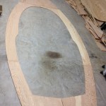
Hull Sides

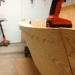
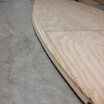
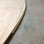
IMG_2646IMG_2635Before you can begin the hull side assembly, the hull bottom and deck assemblies must be completed.
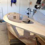
IMG_2650IMG_2651Then we start with the transom.
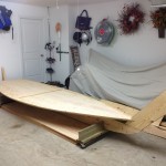
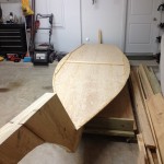
IMG_2658IMG_2657Next is to place the completed deck assembly on top of the bulk heads and the tip of the stern.  These will be attached later.
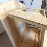
IMG_2652IMG_2653Now the Lazarette is attached to the bottom stringer.  Notice how there is no curvature in either component.  This is the fun part and will require a lot of muscle power to attach.

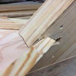
IMG_2654IMG_2655I ended up with a 2″ shortage some how when I pulled the Transom and deck together. When I tried to attach the two it pulled away from the stern block.
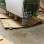
IMG_2648IMG_2647To help make this easier, I put my 9′ christmas tree which seems to weigh a ton on top of paint cans centered on the Lazarrette and Transom pieces for several days.
IMG_2656After shifting everything around, something changed and this actually worked pretty well and everything lined up.  I would still recommend some extra help so your hands are free to glue and screw all the components together properly.

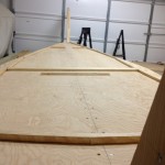
Now notice here that there is a little extra curvature across the top of the deck.  After all the stress of the previous gapping, I messed up here and should have laid the deck across the top of these parts to create a curved deck.  Opps!

IMG_2704So the deck turned out to be flat between the Transom and the Lazzarette, but I actually don’t mind it this way.  The hatch will be easier to build.

*** Now at this point I took things out of order from the plan and build the cabin walls, rafters and roof, hatch openings and surrounding stringers, mast box, bow gussets, bowsprit bits and anything else that would be easier to do without having to climb in and out of the boat, before I put the hull sides on. ***
IMG_2724IMG_2725

Fore Starboard panel.

IMG_2729IMG_2730

Aft Starboard panel.

IMG_2731IMG_2734

Both sides complete.

IMG_2722IMG_2736

Before / After
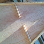
Bulk Heads

IMG_2633At the top is the cabin bulk head, and the bottom is the forward bulk head.

IMG_2634

Here below the bulk heads are the Lazzarette at the top and the Transom at the bottom.

Hull Bottom

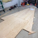
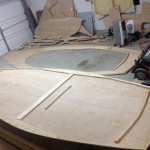
Here I laid out all the hull bottom pieces.  Notice the short stringers in the center, placed to hold the larger sheets of plywood together temporarily.

IMG_2610

In this picture you will see a better view of the triangular wings on the sides.  These are here because the boat is actually wider than the stock plywood.

IMG_2613

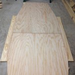
Here the wings are cut shorter and if you look close you may be able to see the curvature outline.

IMG_2615

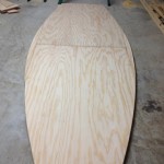
All trimmed up with the finished lines.

IMG_2616IMG_2617

A closer look at the curve lines.  This is a lot easier than you would think, just take your time.

IMG_2620IMG_2621

Next the bottom assembly is set on top of the keel assembly.

IMG_2623IMG_2622

Here you can see the notch that is needed for the bottom assembly to fit into the keel assembly.  Then you attach, glue and screw, the two assemblies together.

IMG_2646IMG_2649

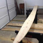
Stringers, Stringer, Stringer!

This is a great view of most of the stringers on the bottom and deck assemblies.

IMG_2644

Forward bulk head stringer.

IMG_2643

Cabin/Companion Way stringer and central joiner.

IMG_2642

Transom and Lazarrette stringers.

Keel Assembly

1st Day…delivery of the wood.  I can’t wait to get started!

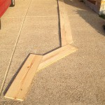
The first step in this project is to create the keel.  Here you can see the 1st layer of 1×12 stock laid flat and marked with nails to outline the cuts to be made.

After the first cuts are made you can see the curvature of the bow end of the keel.
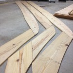
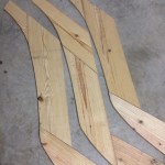
There are three pieces of stock that make the entire length of the keel.  Here they are all laid out.

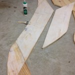
Next the different cut pieces are stacked on top of one another to create the outline for a second set. This is performed a third time, but the middle layer will be off set to create an overlapping effect and more stability of the entire keel.

Here you can see the three separate layers of the keel at the bow end.
Now the three layers looking aft.
Next all the layers are glued and screwed together.  The video shows the use of ring nails, but I chose to use screws for a stronger keel.  The plan even says that it is a good idea but not required.
Here everything is stacked together at the bow.
All stacked together after glueing.  If you look closely you can see the gentle curve of the hull bottom, but there is no curve on the bottom of the keel per the plans instructions.  This is because I decided to modify the plans here a little and will keep the keel full size the entire length so I can mount an electric motor to the bottom of the boat vial a cutout with the keel.  More on that later…
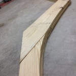
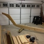
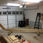
Here you can see the entire assembly completed.
The Keel assembly resting on a homemade stand, which was simply made of some scrap 2×6 in an inverted T shape with a notch cut out for the keel to stand upright, and casters placed on the bottom for easy mobility around the shop.        If you look closely you can see the gentle curve on the top of the keel for the hull bottom, but there is no curve on the bottom of the keel per the plans instructions.  This is because I decided to modify the plans here a little and will keep the keel full size the entire length so I can mount an electric motor to the bottom of the boat.  You can see a cutout at the aft end of the keel.  More on that later…